[Now Reading] Large-batch training for Deep Learning: Generalization gap and Minima

Title: Large-batch training for Deep Learning: Generalization gap and Minima
Authors: Nitish Shirish Keskar, Dheevatsa Mudigere, Jorge Nocedal, Mikhail Smelyanskiy, Ping Tak Peter Tang
Link: https://arxiv.org/abs/1609.04836

Quick summary:
The main goal of this paper is to discuss about the minimizers resulting from using large and small batch size and to provide with a measure of how sharp is the minimum found. Loss functions depend on both the geometry of the cost function and the size and properties of the training set. Using batches have been proven to converge to minimizers and stationary points of strongly-convex functions, avoid saddle-points and robustness to input data, but a large batch size is shown to lead to a loss in generalization performance (generalization gap).

They observe that this loss of generalization is related to the sharpness of the minimizer obtain by large-batch (LB) methods. On the other hand, methods using small batch (SB) lead to flatter minimizers.

flat-sharpminimizers

There is a clear trade-off because LB are desirable since they are computationally efficient and less noisy but if they are too large they will not generalize well. They mention some reasons why this might happen: 1) LB methods produce overfitting, 2) they are attracted to saddle points, 3) they lack the exploratory properties SB has, 4) and they tend to zoom-in on the minimizer closest to the initial point. They had a look at the minimizers and realized that sharp minimizers have significantly large positive eigenvalues whereas flat minimizers have small eigenvalues, thus their conclusion is that the sharpness of a minimizer can be characterized by the magnitude of the eigenvalues [latex]\nabla^2 f(x)[/latex].

For this reason, they come up with a formula to measure the sharpness of a function, and the results show that it can distinguish quite well how different it is the minimizer when large and small batches are used. This measure is basically based on drawing a small box around the minimizer and check largest value. However, a minimizer does not usually have the shape of a cone. Values at one side can be very large whereas on the other side be flatter.

drawing1

They try to improve the generalization problem of LB by doing data augmentation, conservative training and adversarial training and although they help to reduce the generalization gap, they do not solve the problem completely. They also experiment combining small and large batches and hypothesize that a gradual increase of the batch size might help the generalization process.

The authors observe that the noisy in the gradient when using SB pushes the iterates out of sharp minimizers, thus encouraging movement towards a flatter minimizer. They also observe that LB methods are usually attracted to minimizers close to the starting point and, in contrast, SB tend to go further away.

[Now Reading] Qualitatively Characterizing Neural Network Optimization Problems

Title: Qualitatively characterizing neural network optimization problems
Authors: Ian J. Goodfellow, Oriol Vinyals, Andrew M. Saxe
Link: https://arxiv.org/abs/1412.6544

Quick Summary:
The main goal of the paper is to introduce a simple way to look at the trajectory of the weights optimization. They also mention that it might be possible that some NN are difficult to train due to the effect of their complex structures in the cost function or the noisy introduced in the minibatches because they didn’t find that local minima and saddle points slow down the SGD learning.

This technique consist in evaluating [latex]J(\theta)[/latex] (the cost function) where [latex]\theta = (1-\alpha) \theta_0 + \alpha \theta_1[/latex] for different values of [latex]\alpha[/latex]. They set [latex]\theta_0 = \theta_i[/latex] (initial weights) and [latex]\theta_1 = \theta_f[/latex] (weights after training), and we can get a cross-section of the objective function.

paper1

We can see thus whether there are some bumps or flats during the training given the training/testing data. They do not mention if they averaged the costs obtained with the training and testing datasets, but I guess so because otherwise they would be significantly different.

Difference between L1 and L2 regularization, implementation and visualization in Tensorflow

Regularization is a technique used in Machine Learning to penalize complex models. The reason why regularization is useful is because simple models generalize better and are less prone to overfitting.

models_2

Examples of regularization:

  • K-means: limiting the splits to avoid redundant classes
  • Random forests: limiting the tree depth, limiting new features (branches)
  • Neural networks: limiting the model complexity (weights)

In Deep Learning there are two well-known regularization techniques: L1 and L2 regularization. Both add a penalty to the cost based on the model complexity, so instead of calculating the cost by simply using a loss function, there will be an additional element (called “regularization term”) that will be added in order to penalize complex models.

reg_formulas

The theory

L1 regularization (LASSO regression) produces sparse matrices. Sparse matrices are zero-matrices in which some elements are ones (the sparsity refers to the ones), but in this context a sparse matrix could be several close-to-zero values and other larger values. From the data science point of view this is interesting because we can reduce the amount of features. If we find a model with neurons whose weights are close to zero it means we don’t need those neurons because the model deactivates them with zeros and we might not need a specific feature/input leading to a simpler model. For instance, if we have 50 coefficients but only 10 are non-zero, the other 40 are irrelevant to make our predictions. This is not only interesting from the efficiency point of view but also from the economic point of view: gathering data and extracting its features might be a very expensive task (in terms of time and money). Reducing this will benefit us.

Due to the absolute value, L1 regularization provides with a non-differentiable term, but despite of that, there are methods to minimize it. As we will see below, L1 regularization is also robust to outliers.

L2 regularization (Ridge regression) on the other hand leads to a balanced minimization of the weights. Since L2 uses squares, it emphasizes the errors, and it can be a problem when there are outliers in the data. Unlike L1, L2 has an analytical solution which makes it computationally efficient.

Both regularizations have a λ parameter which is directly proportional to the penalty: the larger λ the stronger penalty to find complex models and it will be more likely that the model will avoid them. Likewise, if λ is zero, regularization is deactivated.

regularization

The graphs above show how the functions used in L1 and L2 regularization look like. The penalty in both cases is zero in the center of the plot, but this also implies that the weights are zero and the model will not work. The values of the weights try to be as low as possible to minimize this function, but inevitably they will leave the center and will head outside. In case of L2 regularization, going towards any direction is okay because, as we can see in the plot, the function increases equally in all directions. Thus, L2 regularization mainly focuses on keeping the weights as low as possible.

In contrast, L1 regularization’s shape is diamond-like and the weights are lower in the corners of the diamond. These corners show where one of the axis/feature is zero thus leading to sparse matrices. Note how the shapes of the functions shows their differentiability: L2 is smooth and differentiable and L1 is sharp and non-differentiable.

In few words, L2 will aim to find small weight values whereas L1 could put all the values in a single feature.

L1 and L2 regularization methods are also combined in what is called elastic net regularization.

The practice

One of my motivations to try this out was an “intuitive explanation” of L1 vs. L2 I found in quora.

main-qimg-ed279c02762abdb8c5fa3db3f200b823

From the theoretical point of view it makes sense: L2 emphasizes errors due to the square, and it will try to minimize them all of them equally so the line will get a bit off from the main trend because a big errors influences more than small errors. On the other hand, for L1 errors have the same importance (linearly speaking) so it will minimize a lot of errors getting really close to the main train even if there are outliers.

I created a small dataset of samples that describes a straight line and I later added noise and some outliers. I created a model with more neurons than needed to solve this problem in order to see whether it works and compare the weight evolution between the methods.

Model characteristics:
-Layers: 1 input, 3 hidden, 1 output
-Sizes: 1,10,10,10,1
-Batch size: 1 (noiser)
-Optimizer: SGD (lr=0.01)
-Lambda: 0.3 (for regularization)

I run the model 5 times with each regularization method and these are the results.

all_results

When the random outliers are sufficiently far none of them present good results, but overall the results obtained with L2 performance were better than those obtained with L1. Then, I had a look at the weights. Below, I show the weights and the results obtained with an additional run of the model.

L1_final_n l1_compressed
L2_final_n l2_compressed

As expected, L1 generates several 0-weighted neurons, so the model doesn’t use them. In other experiments, I got that most of the neurons were disconnected and only few of them had non-zero weights. On the other hand, L2 minimizes the values of the weights until most of them have a very low value.

Adjusting the network according to L1

As described before, L1 generates sparse matrices with disconnected neurons. If a neuron is disconnected, we don’t need it, leading to simpler models. I run again the script that uses L1 and I will adjust the model using less neurons according to the neurons it disconnects. Using the same samples and running the model 5 times, I got this total errors: 22.68515524, 41.64545712, 4.77383674, 24.04390211, 7.25596004.

The weights in this first run look like this:

iter1_compressed

I adjusted the neurons of the model: From [(1,10),(10,10),(10,10),(10,1)] to [(1,10),(10,10),(10,1),(1,1)] and this are the weights (note: the last big square is a single weight):

iter2_compressed

Performance on 5 runs: 7.61984439, 13.85177842, 11.95983347, 16.95491162, 25.17294774.

Implementation in Tensorflow

Despite the code is provided in the Code page as usual, implementing L1 and L2 takes very few lines: 1) Add regularization to the Weights variables (remember the regularizer returns a value based on the weights), 2) collect all the regularization losses, and 3) add to the loss function to make the cost larger.

with tf.variable_scope("dense1") as scope:
    W = tf.get_variable("W",shape=[1,10],initializer=tf.contrib.layers.xavier_initializer(),regularizer=tf.contrib.layers.l2_regularizer(lambdaReg))
...
reg_losses = tf.reduce_sum(tf.get_collection(tf.GraphKeys.REGULARIZATION_LOSSES))
cost = tf.reduce_sum(tf.abs(tf.subtract(pred, y)))+reg_losses

Conclusion

The performance of the model depends so much on other parameters, especially learning rate and epochs, and of course the number of hidden layers. Using a not-so good model, I compared L1 and L2 performance, and L2 scores were overall better than L1, although L1 has the interesting property of generating sparse matrices.

Hypothetical improvements: This post aimed to show in a very simple and graphic/animated way the effects of L1 and L2. Further research would imply trying more complex models with data that gives stable results. After tunning the parameters to get the best results, one could use cross validation to compare better the performance.

The code is provided in the Source code section.

How to freeze a graph in Tensorflow

I run into this issue when I was interested in freezing graphs for using them in mobile devices. Freezing a Graph means combining the structure of a model with its weights, so first we need to save those two parts to later combine them.

Saving the structure

# "g" will be your Graph
g = sess.graph
# In my case, I use the default Graph
gdef = g.as_graph_def()
# Parameters: 1) graph, 2) directory where we want to save the pb file,
#             3) name of the file, 4) text format (True) or binary format.
tf.train.write_graph(gdef,".","graph.pb",False)

Note: if we save our graph as text, setting the boolean value to True, we can have a look at it with any text editor and see how it looks like. Since it uses Protocol Buffers it is easily readable.

Saving the weights

We also call this the checkpoints. We have to get a Saver object and use it after the network is trained so it will contained the weights obtained after the optimization.

# When defining the model
saver = tf.train.Saver()
# ....
# After the model is trained
saver.save(sess, 'tmp/my-weights')

Freezing the Graph

Now it’s time to combine both files. We can see the commands in the original tutorial in github.

Since I didn’t want to mess up with my current tensorflow library, I downloaded tensorflow again in a separate folder

git clone https://github.com/tensorflow/tensorflow.git

After I installed Bazel (following their website instructions) I tried to build the freeze_graph (make sure you are in the right path. If you download again tensorflow from github note that it has a “WORKSPACE” file. You should be there to run Bazel) by doing:

bazel build tensorflow/python/tools:freeze_graph

It takes a while to build it. In MacOS Sierra I didn’t have any problem, but in Ubuntu 16.04 I did, and after searching I found on github how to solve it.

bazel build -c opt --copt=-msse4.1 --copt=-msse4.2 tensorflow/python/tools:freeze_graph

After this, in the same folder, we just need to execute the command provided in the tutorial:

bazel-bin/tensorflow/python/tools/freeze_graph\
    --input_graph=/tmp/mobilenet_v1_224.pb \
    --input_checkpoint=/tmp/checkpoints/mobilenet-10202.ckpt \
    --input_binary=true --output_graph=/tmp/frozen_mobilenet_v1_224.pb \
    --output_node_names=MobileNet/Predictions/Reshape_1

input_graph: location of the structure of the graph (first part of the tutorial, pb file)
input_checkpoint: weights stored using the Saver (second part of the tutorial)
input_binary=true: remember to save the graph in binary format. They recommend that this value has to be true, so do not use text format generating the pb file.
output_graph: location of the new frozen graph
output_node_names: name of the output node. You can check this using Tensorboard, but assuming you are naming all the tensors, this should be easy to figure out. You can also check the name of all the operations, or check the pb file (text mode), but probably the most intuitive way is using Tensorboard.

After executing this, we will have our frozen graph.

Bonus: How to use the frozen Graph in Python

Here I found a very easy to follow code that explains itself how to read a frozen Graph to use it.

import tensorflow as tf

def load_graph(frozen_graph_filename):
    # We load the protobuf file from the disk and parse it to retrieve the
    # unserialized graph_def
    with tf.gfile.GFile(frozen_graph_filename, "rb") as f:
        graph_def = tf.GraphDef()
        graph_def.ParseFromString(f.read())

    # Then, we import the graph_def into a new Graph and returns it
    with tf.Graph().as_default() as graph:
        # The name var will prefix every op/nodes in your graph
        # Since we load everything in a new graph, this is not needed
        tf.import_graph_def(graph_def, name="prefix")
    return graph

Activation Functions in Deep Learning (Sigmoid, ReLU, LReLU, PReLU, RReLU, ELU, Softmax)

Sigmoid and its main problem

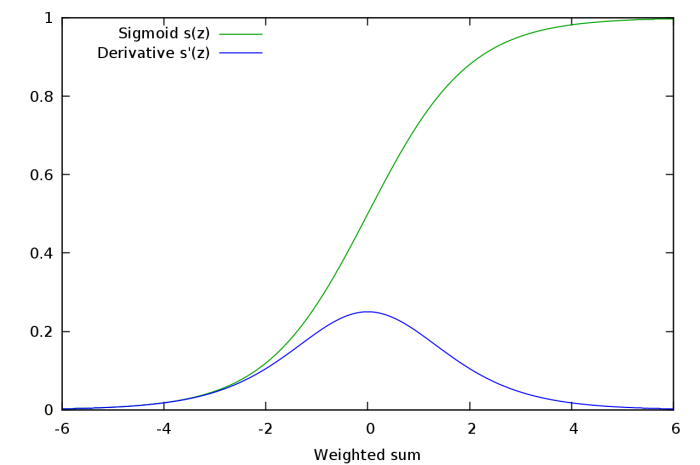
Sigmoid function has been the activation function par excellence in neural networks, however, it presents a serious disadvantage called vanishing gradient problem. Sigmoid function’s values are within the following range [0,1], and due to its nature, small and large values passed through the sigmoid function will become values close to zero and one respectively. This means that its gradient will be close to zero and learning will be slow.

This can be easily seen in the backpropagation algorithm (for a simple explanation of backpropagation I recommend you to watch this video):

[latex]-(y-\hat{y}) f’ (z) \frac{\partial z}{\partial W}[/latex]

where [latex]y[/latex] is the prediction, [latex]\hat{y}[/latex] the ground truth, [latex]f'()[/latex] derivative of the sigmoid function, [latex]z[/latex] activity of the synapses and [latex]W[/latex] the weights.

The first part [latex]-(y-\hat{y}) f’ (z)[/latex] is called backpropagation error and it simply multiplies the difference between our prediction and the ground truth times the derivative of the sigmoid on the activity values. The second part describes the activity of each synopsis. In other words, when this activity is comparatively larger in a synapse, it has to be updated more severely by the previous backpropagation error. When a neuron is saturated (one of the bounds of the activation function is reached due to small or large values), the backpropagation error will be small as the gradient of the sigmoid function, resulting in small values and slow learning per se. Slow learning is one of the things we really want to avoid in Deep Learning since it already will consist in expensive and tedious computations. The Figure below shows how the derivative of the sigmoid function is very small with small and large values.

Sigmoid function and its derivative

Conclusion: if after several layers we end up with a large value, the backpropagated error will be very small due to the close-to-zero gradient of the sigmoid’s derivative function.

ReLU activation function

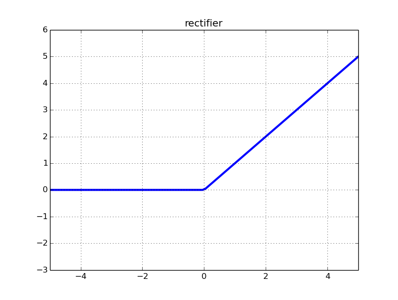
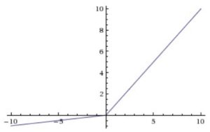
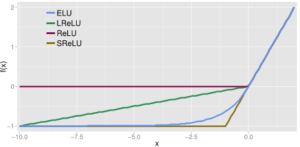
ReLU (Rectified Linear Unit) activation function became a popular choice in deep learning and even nowadays provides outstanding results. It came to solve the vanishing gradient problem mentioned before. The function is depicted in the Figure below.

ReLU

The function and its derivative:
latex
f(x) = \left \{ \begin{array}{rcl}
0 & \mbox{for} & x < 0\\ x & \mbox{for} & x \ge 0\end{array} \right. latex latex f'(x) = \left \{ \begin{array}{rcl} 0 & \mbox{for} & x < 0\\ 1 & \mbox{for} & x \ge 0\end{array} \right. /latex In order to understand why using ReLU, which can be reformulated as [latex]f(x) = max(0,x)[/latex], is a good idea let's divide the explanation in two parts based on its domain: 1) [-∞,0] and 2) (0,∞]. 1) When the synapse activity is zero it makes sense that the derivative of the activation function is zero because there is no need to update as the synapse was not used. Furthermore, if the value is lower than zero, the resulting derivative will be also zero leading to a disconnection of the neuron (no update). This is a good idea since disconnecting some neurons may reduce overfitting (as co-dependence is reduced), however this will hinder the neural network to learn in some cases and, in fact, the following activation functions will change this part. This is also refer as zero-sparsity: a sparse network has neurons with few connections.

2) As long as values are above zero, regardless of how large it is, the gradient of the activation function will be 1, meaning that it can learn anyways. This solves the vanishing gradient problem present in the sigmoid activation function (at least in this part of the function).

Some literature about ReLU [1].

LReLU activation function

Leaky ReLU is a modification of ReLU which replaces the zero part of the domain in [-∞,0] by a low slope, as we can see in the figure and formula below.

leaky.png

The function and its derivative:

latex
f(x) = \left \{ \begin{array}{rcl}
0.01 x & \mbox{for} & x < 0\\ x & \mbox{for} & x \ge 0\end{array} \right. latex latex f'(x) = \left \{ \begin{array}{rcl} 0.01 & \mbox{for} & x < 0\\ 1 & \mbox{for} & x \ge 0\end{array} \right. latex The motivation for using LReLU instead of ReLU is that constant zero gradients can also result in slow learning, as when a saturated neuron uses a sigmoid activation function. Furthermore, some of them may not even activate. This sacrifice of the zero-sparsity, according to the authors, can provide worse results than when the neurons are completely deactivated (ReLU) [2]. In fact, the authors report the same or insignificantly better results when using PReLU instead of ReLU.

PReLU activation function

Parametric ReLU [3] is a inspired by LReLU wich, as mentioned before, has negligible impact on accuracy compared to ReLU. Based on the same ideas that LReLU, PReLU has the same goals: increase the learning speed by not deactivating some neurons. In contrast with LReLU, PReLU substitutes the value 0.01 by a parameter [latex]a_i[/latex] where [latex]i[/latex] refers to different channels. One could also share the same values for every channel.

The function and its derivative:

latex
f(x) = \left \{ \begin{array}{rcl}
a_i x & \mbox{for} & x < 0\\ x & \mbox{for} & x \ge 0\end{array} \right. latex latex f'(x) = \left \{ \begin{array}{rcl} a_i & \mbox{for} & x < 0\\ 1 & \mbox{for} & x \ge 0\end{array} \right. latex The following equation shows how these parameters are iteratevely updated using the chain rule as the weights in the neural network (backpropagation). [latex]\mu[/latex] is the momentum and [latex]\epsilon[/latex] is the learning rate. IN the original paper, the initial [latex]a_i[/latex] used is 0.25 [latex]\nabla a_i := \mu \nabla a_i + \epsilon \frac{\partial \varepsilon}{\partial a_i}[/latex]

RReLU activation function

Randomized ReLU was published in a paper [4] that compares its performance with the previous rectified activations. According to the authors, RReLU outperforms the others, and LReLU performs better when [latex]\frac{1}{5.5}[/latex] substitutes 0.01.

rrelu

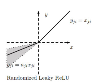
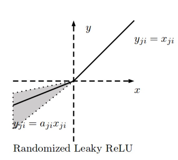
The negative slope of RReLU is randomly calculated in each training iteration such that:

[latex]f_{ji}(x) = \left \{ \begin{array}{rcl} \frac{x_{ji}}{a_{ji}} xa & \mbox{for} & x_{ji} \ge 0\\ x_{ji} & \mbox{for} & x_{ji} \ge 0\end{array} \right.[/latex]

where
[latex]a_{ji} \sim U(l,u)[/latex]

The motivation to introduce a random negative slope is to reduce overfitting.

[latex]a_{ji}[/latex] is thus a random number from a uniform distribution bounded by [latex]l[/latex] and [latex]u[/latex] where [latex]i[/latex] refers to the channel and [latex]j[/latex] refers to the example. During the testing phase, [latex]a_{ji}[/latex] is fixed, and an average of all the [latex]a_{ji}[/latex] is taken: [latex]a_{ji} = \frac{l+u}{2}[/latex]. In the paper they use [latex]U(3,8)[/latex] and in the test time [latex]a_{ji} = \frac{11}{2}[/latex].

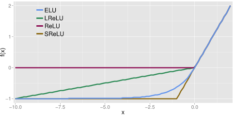
ELU activation function

Exponential Linear Unit (ELU) is another type of activation function based on ReLU [5]. As other rectified units, it speeds up learning and alleviates the vanishing gradient problem.

elu

Similarly to the previous activation functions, its positive part has a constant gradient of one so it enables learning and does not saturate a neuron on that side of the function. LReLU, PReLU and RReLU do not ensure noise-robust deactivation since their negative part also consists on a slope, unlike the original ReLU or ELU which saturate in their negative part of the domain. As explained before, saturation means that the small derivative of the function decreases the information propagated to the next layer.

The activations that are close to zero have a gradient similar to the natural gradient since the shape of the function is smooth, thus activating faster learning than when the neuron is deactivated (ReLU) or has non-smooth slope (LReLU).

The function and its derivative:

[latex]f(x) = \left \{ \begin{array}{rcl} \alpha (exp(x) – 1) & \mbox{for} & x \le 0\\ x & \mbox{for} & x > 0\end{array} \right.[/latex]
[latex]f'(x) = \left \{ \begin{array}{rcl} f(x) + \alpha & \mbox{for} & x \le 0\\ 1 & \mbox{for} & x > 0\end{array} \right.[/latex]

In a nutshell:

  1. Gradient of 1 in its positive part.
  2. Deactivation on most of its negative domain.
  3. Close-to-natural gradient in values closer to zero.

Softmax activation function

For the sake of completeness, let’s talk about softmax, although it is a different type of activation function.

Softmax it is commonly used as an activation function in the last layer of a neural network to transform the results into probabilities. Since there is a lot out there written about softmax, I want to give an intuitive and non-mathematical reasoning.

Case 1:
Imagine your task is to classify some input and there are 3 possible classes. Out of the neural network you get the following values (which are not probabilities): [3,0.7,0.5].

It seems that it’s very likely that the input will belong to the first class because the first number is clearly larger than the others. But how likely is it? We can use softmax for this, and we would get the following values: [0.846, 0.085, 0.069].

Case 2:
Now we have the values [1.2,1,1.5]. The last class has a larger value but this time is not that certain whether the input will belong to that class but we would probably bet for it, and this is clearly represented by the output of the softmax function: [0.316, 0.258, 0.426].

Case 3::
Now we have 10 classes and the values for each class are 1.2 except for the first class which is 1.5: [1.5,1.2,1.2,1.2,1.2,1.2,1.2,1.2,1.2,1.2]. Common sense says that even if the first class has a larger value, this time the model is very uncertain about its prediction since there are a lot of values close to the largest one. Softmax transforms that vector into the following probabilities: [0.13, 0.097, 0.097, 0.097, 0.097, 0.097, 0.097, 0.097, 0.097, 0.097].

Softmax function:

[latex size=”25″]\sigma (z)_j = \frac{e^{z_j}}{\sum^K_{k=1} e^{z_j}}[/latex]

In python:

z_exp = [math.exp(i) for i in z]
sum_z_exp = sum(z_exp)
return [round(i/sum_z_exp, 3) for i in z_exp]

References

1. Nair V. & Hinton G.E. 2010. “Rectified Linear Units Improve Restricted Boltzmann Machines”
2. Maas A., Hannun A.Y & Ng A.Y. 2013. “Rectifier Nonlinearities Improve Neural Network Acoustic Models”
3. He K., Zhang X., Ren S. & Sun J. 2015. “Delving Deep Into Rectifiers: Surpassing Human-Level Performance on ImageNet Classification”
4. Xu B., Wang N., Chen T. & Li M. 2015. “Empirical Evaluation of Rectified Activations in Convolutional Network”
5. Clevert D.A., Unterthiner T. & Hochreiter S. 2016. Fast and Accurate Deep Network Learning by Exponential Linear Units (ELUs)

Colorizing black and white images using Deep Learning (Tensorflow)

Recently I was reading up on an interesting paper that explores how colorizing black and white images using Deep Learning. The paper was easy to read and understand, and to fully enjoy it I decided to implement it in a lower scale. I have a laptop with a humble graphic card and an i7 so it cannot compete with those servers that cost several thousand euros, that is why I have not focused on the design of the network but more on the algorithmic part.

Goals and dataset

The goals of this post are:

  1. To be able to implement the algorithm to learn about a new colorizing approach.
  2. To have a look to the neural network they used.
  3. To figure out if a simpler network can learn even if the results are quite improvable.
  4. To practice using tensorflow.
  5. To have fun.

The dataset I will use can be downloaded here. It consist of 2687 256×256 images of beaches, forests, streets, etc.

Algorithm

One of the things I enjoyed about the paper [1] is how well structured it is, which made the understanding much easier. I will try to follow their structure in a similar way while being precise and concise.

The very first important thing we need to know is that Lab color space is used. The reason is simple: in color spaces such as RGB we need to learn three different channels whereas in Lab we only need to learn two. The channel L refers to the lightness, having values between 0 (dark) and 100. The channels a and b are the position in the axis between red-green and blue-yellow respectively.

63c89aba0ed994edcfce462b2a4b2b6b

A typical approach would use the L channel as input and the a,b channels as output (for every pixel the prediction consists on two values). However, they argue that using a loss function based on two components does not represent the multimodal and ambiguity problems properly. We are surrounded by objects that can have multiple colors such as apples since they can be red, green or yellow. In addition, Euclidian distance (averaging) will increase desaturated (grayish) values.

In order to solve this they divided the a,b colorspace into Q bins corresponding to probabilities, and consequently, the number of predictions expected per pixel will be Q (one per bin). For instance, in case of the apple, the bins corresponding to red, yellow and green will contain higher probabilities than those bins close to colors like blue.

colorspace

I skipped representing some bins by analyzing first the colors I have in my dataset so that I only take into account those bins with colors used in my dataset. My a,b color space is between -110 and 110 and depending on the size of the squared window used to divide it, the resulting grid and the final used bins will be different. When I’m using the whole dataset and a window size of 10 I use XX bins and it raises to XXX bins when the window size is 5. In contrast, the authors use Q=313 bins.

The problem is now a simple classification problem in which we have an input (brightness values) and the output is a set of probabilities indicating how likely are the values to belong to a certain bin. A classic way to solve this is to use cross entropy but in addition to it, the authors noticed that the model is biased towards low a,b values which typically correspond to backgrounds such as walls, sky, etc. In order to solve this, they rebalanced the colors by adding weights that will multiply the cross entropy calculated.

form1

This formula can be read as: perform cross-entropy on a pixel comparing the original and predicted distribution of the probabilities, and then multiply it by a weight corresponding to that color such that certain colors are highlighted to the network.

form2

To calculate these weights they introduced a new hyper-parameter [latex]\lambda[/latex] (they use [latex]\lambda=0.5[/latex]). Q was the number of bins used and [latex]\tilde{p}[/latex] is a distribution calculated from our dataset. I tried to use the full dataset consisting of different types of images and another consisting only of images of forests so I had to recalculated it. You can count the number of pixels that are located within each bin and later normalize it. They also apply a Gaussian kernel but I actually skipped that part. The image below depicts which colors are used the most in the dataset.

colorspacecombined

In the image above, the left side shows that the most used colors are located in the center (desaturated) and both cases differ depending on the dataset: when only forest images were used, less pink-red colors were used.

This is basically all, in regards to the training part. The other important issue arises when predicting values. Imagine for a second that for a single pixel the network spits a probability distribution such that all values are zero except for one value that is one (the so called one-hot vector). It is more than clear that the corresponding bin will represent the color of that pixel. Nonetheless, we will probably have several probabilities and mapping them back to a,b values is the next task. They introduced a new variable called T standing for temperature (coming from simulated annealing). To put it simple, when T tends to zero, values are more intense since the prediction emphasizes the color with the highest probability. On the other hand, when T tends to one, the colors are more distributed but also more desaturated because the color is result of a more spread average of the obtained probabilities.

form3

The formula above describes how they calculated the prediction given the temperature T and the distribution z.

Neural Network

As I have mentioned before, due to my limited resources, utilizing the network they used was immediately discarded. Thus I designed a very simple neural network that consists of 8 convolutional layers. The input consist of a window of 32×32 pixels and after the convolutions the final prediction has a size of 16×16. In every convolution the size is reduced by 2 because of the 3×3 kernel thus reducing one pixel on each side of the image. The number of filters used depends on the number of bins Q such that they are growing using a step of Q/8. For instance, the number of filters in the first convolutional layer is Q/8, in the second layer is 2*Q/8, and so on until the last layer with a number of Q filters. Therefore, the size of my final output will be 16x16xQ.

Results

At first I was using only the forest dataset to speed up the training process and regardless of some hyper-parameters tunning the results were a bit random: sometimes they were quite okay and sometimes they were bad, but in all cases the network was learning and showing a behavior that makes sense, so I can say that I am satisfied with the results.

results_color

The code is provided in the Source code section.

References

1. Zhang R., Isola P. & Efros A.A. 2016. Colorful Image Colorization.

Informal review on Randomized Leaky ReLU (RReLU) in Tensorflow

This very informal review of the activation function RReLU compares the performance of the same network (with and without batch normalization) using different activation functions: ReLU, LReLU, PReLU, ELU and an less famous RReLU. The difference between them lies on their behavior from [latex][- \infty,0][/latex]. The goal of this entry is not to explain in detail these activation functions, but to provide a short description.

When a negative value arises, ReLU deactivates the neuron by setting a 0 value whereas LReLU, PReLU and RReLU allow a small negative value. In contrast, ELU has a smooth curve around the zero to make it derivable resulting in a more natural gradient and instead of deactivating the neuron negative values are mapped into a negative one. The authors claim that this pushes the mean unit closer to zero, like batch normalization [1].

elu

LReLU, PReLU and RReLU provide with negative values in the negative part of the respective functions. LReLU is using a small tilted slope whereas PReLU learns the steepness of this slope. On the other hand, RReLU, the function we will study here, sets this slope to be a random value between an upper and lower bound during the training and an average of these bounds during the testing. The authors of the original paper get their inspiration from Kaggle competition and even use the same values [2]. These are random values between 3 and 8 during the training and a fixed value 5.5 during testing.

Notice that in [2] and consequently in the following tests, the variable [latex]\alpha_i[/latex] that uses LReLU is not used as [latex]\alpha_i x_i[/latex] but as [latex]\frac{x_i}{\alpha_i}[/latex]. This detail is important and for some reasons [2] change the notation from the original LReLU paper.

Results

As in the paper where RReLU is introduced, I used the same activation function configurations plus ELU (default configuration). I run a very simple neural network using MNIST dataset with and without batch normalization and as we can see in the figure below RReLU does not only perform among the words but the simple ReLU performs the best when normalization is used and almost the best when no normalization is added.

fixed_norm

fixed_nonorm

Notes on Tensorflow

This activation function requires to constantly use new random values that need to be initalized constantly while the network is training. As we can see in the corresponding tutorial video and the source code the initializer needs to be called on each iteration during the training by:

sess.run(r1.initializer)

The code is provided in the Source code section.

References

1. Clevert D.A., Unterthiner T. and Hochreiter S. 2016. Fast and accurate Deep Network Learning by Exponential Linear Units (ELUs). ICLR 2016.
2. Xu B., Wang N., Chen T. and Li M. 2015. Empirical Evaluation of Rectified Activations in Convolutional Network.

Debugging a Keras Neural Network

Learning outcomes:

  • How to get the weights and bias values of the layers.
  • How to get the values between the hidden layers (before and after the activation function)

The goal of this post is to learn how to debug a neural network in Keras. This is extremely important due to a variety of reasons.

  1. Knowing how to debug increases the understanding of the underlying structure of the network and its theoretical background.
  2. Learning what’s going on at each level of the network translates into a better understanding of the outcome.
  3. Knowing about each layer’s outcome can be valuable for research purposes.
  4. Meticulous analyses and splits of the network allow us to easily replace and experiment with some parts of it.

Obtaining general information

Obtaining general information can give us an overview of the model to check whether its components are the ones we initially planned to add. We can simply print the layers of the model or retrieve a more human-friendly summary. Note that the layer of the neural network (input, hidden, output) are not the same as the layers of the Keras model. Our model’s layers are more abstract operations such that transformations, convolutions, activations, etc.

print(model.layers)

Output:

[<keras.layers.convolutional.Conv2D at 0x7faf0c4c9c90>,
 <keras.layers.convolutional.Conv2D at 0x7faf0c4de050>,
 <keras.layers.pooling.MaxPooling2D at 0x7faf0c46bc10>,
 <keras.layers.core.Flatten at 0x7faf0c4de450>,
 <keras.layers.core.Dense at 0x7faf0c46b690>,
 <keras.layers.core.Dense at 0x7faf0e3cf710>]
print(model.summary())

Output:

_________________________________________________________________
Layer (type)                 Output Shape              Param #  
=================================================================
conv2d_1 (Conv2D)            (None, 26, 26, 32)        320      
_________________________________________________________________
conv2d_2 (Conv2D)            (None, 24, 24, 64)        18496    
_________________________________________________________________
max_pooling2d_1 (MaxPooling2 (None, 12, 12, 64)        0        
_________________________________________________________________
flatten_1 (Flatten)          (None, 9216)              0        
_________________________________________________________________
dense_1 (Dense)              (None, 128)               1179776  
_________________________________________________________________
dense_2 (Dense)              (None, 10)                1290      
=================================================================
Total params: 1,199,882
Trainable params: 1,199,882
Non-trainable params: 0
_________________________________________________________________

We can also retrieve each layer’s input and output size.

for layer in model.layers:
    print("Input shape: "+str(layer.input_shape)+". Output shape: "+str(layer.output_shape))

Output:

Input shape: (None, 28, 28, 1). Output shape: (None, 26, 26, 32)
Input shape: (None, 26, 26, 32). Output shape: (None, 24, 24, 64)
Input shape: (None, 24, 24, 64). Output shape: (None, 12, 12, 64)
Input shape: (None, 12, 12, 64). Output shape: (None, 9216)
Input shape: (None, 9216). Output shape: (None, 128)
Input shape: (None, 128). Output shape: (None, 10)

Obtaining the output of a specific layer after its activation function

This model is a modified example from the original Keras repository.

model = Sequential()
model.add(Conv2D(32, kernel_size=(3, 3),
                 activation='relu',
                 input_shape=input_shape,
         kernel_initializer=keras.initializers.Ones()))

model.add(Conv2D(64, (3, 3), activation='relu', kernel_initializer=keras.initializers.Ones()))
model.add(MaxPooling2D(pool_size=(2, 2)))
model.add(Flatten())
model.add(Dense(128, activation='relu', kernel_initializer=keras.initializers.Ones()))
model.add(Dense(num_classes, activation='softmax', kernel_initializer=keras.initializers.Ones()))

model.compile(loss=keras.losses.categorical_crossentropy,
              optimizer=keras.optimizers.Adam(),
        metrics=['accuracy'])

This model consist of 6 layers which, as we can see in the code, include special information in the parameters. It’s important to note that the activation function used in the layers is specified within the layer because alternatively we could just add another layer after the first convolution specifying the activation function.

We can imagine our model as a tunnel in which each layer is a different part of the tunnel. In order to obtain the output of a specific layer we need to parcellate a subtunnel. As we are interested in the output of the first convolutional layer after the activation function, our subtunnel will be bounded from the input of the first layer to the output of the first layer (which includes the activation funcion because it was specified in the code). We will use the function “function” to create this subtunnel specifying its beginning and end.

from keras import backend as K
fun = K.function([model.layers[0].input],[model.layers[0].output])

After that we simply have to accommodate the input and pass it to that function.

x_inp = np.reshape(x,(1,28,28,1))
layer_output = fun([x_inp])[0]

In the Source code section, the script called debugging1.py shows how subtunnels were created from the beginning to each layer of the network. In addition, it shows an alternative way to obtain the same results providing a good understand of what’s going on in the network and both outcomes are compared to check that they are the same.

Obtaining the output of a specific layer before its activation function

The only difference with regards to the previous section is that this time the model needs to be modified to have its activation functions separated from the layers, as we can see below.

model = Sequential()
model.add(Conv2D(32, kernel_size=(3, 3),
                 input_shape=input_shape,
         kernel_initializer=keras.initializers.Ones()))
model.add(Activation("sigmoid"))

model.add(Conv2D(64, (3, 3), activation='relu', kernel_initializer=keras.initializers.Ones()))
model.add(MaxPooling2D(pool_size=(2, 2)))
model.add(Flatten())
model.add(Dense(128, kernel_initializer=keras.initializers.Ones()))
model.add(Activation("sigmoid"))
model.add(Dense(num_classes, kernel_initializer=keras.initializers.Ones()))
model.add(Activation("softmax"))

model.compile(loss=keras.losses.categorical_crossentropy,
              optimizer=keras.optimizers.Adam(),
        metrics=['accuracy'])

Obtaining the output values is done in a similar way to the previous section. Here we show that obtaining the values before and after the activation it is a matter of changing the output layer.

# With and without the activation
fun_without = K.function([model.layers[0].input],[model.layers[0].output])
fun_with = K.function([model.layers[0].input],[model.layers[1].output])
# Input
x_inp = np.reshape(x,(1,28,28,1))
# Output
layer_output_without = fun_without([x_inp])[0]
layer_output_with = fun_with([x_inp])[0]

In the Source code section, the script called debugging2.py shows this, and as in debugging1.py it also recreates the solution in an alternative way and compare both results.

What if during the training and testing behaviors are different?

Extracted from the Keras website:

Note that if your model has a different behavior in training and testing phase (e.g. if it uses Dropout, BatchNormalization, etc.), you will need to pass the learning phase flag to your function:

get_3rd_layer_output = K.function([model.layers[0].input, K.learning_phase()],
                                  [model.layers[3].output])

# output in test mode = 0
layer_output = get_3rd_layer_output([x, 0])[0]

# output in train mode = 1
layer_output = get_3rd_layer_output([x, 1])[0]

Note how the now the created functor receives both the input and whether it’s training or testing.

Homography estimation explanation and python implementation

Homographies are transformations of images from one planar surface to another (image registration). Homographies are used for tasks such as camera calibrations, 3D reconstruction, image rectifications. There are multiple methods to calculate an homography and this post explains one of the simplest.

Given a point in a 3D space [latex]x=(x_1,y_1,1)[/latex] and a matrix H, the resulting multiplication will return the new location of that point [latex]x’ = (x_2,y_2,1)[/latex] such that:

[latex]x’ = Hx[/latex]

Due to the dimensions of [latex]x[/latex] and [latex]x'[/latex] we know that H will be a 3×3 matrix but even if there are 9 elements in the matrix, we will have just 8 degrees of freedom. In this Powerpoint presentation [1] we can intuitively see where does it come from.

So we have that:

[latex]
\begin{bmatrix}
u \\
v \\
1
\end{bmatrix}
=
\begin{bmatrix}
h_1 & h_2 & h_3 \\
h_4 & h_5 & h_6 \\
h_7 & h_8 & h_9
\end{bmatrix}
\begin{bmatrix}
x \\
y \\
1
\end{bmatrix}
[/latex]

Where [latex]u[/latex] and [latex]v[/latex] are the new coordinates. Therefore, we have:

[latex]
\\
u = x h_1 + y h_2 + h_3 \\
v = x h_4 + y h_5 + h_6 \\
1 = x h_7 + y h_8 + h_9 \\
[/latex]

So for each point we have:

[latex]
\\
x h_1 + y h_2 + h_3 – u (x h_7 + y h_8 + h_9) = 0 \\
x h_4 + y h_5 + h_6 – v (x h_7 + y h_8 + h_9) = 0 \\

A_i =
\begin{bmatrix}
x & y & 1 & 0 & 0 & 0 & -ux & -vy & -u \\
0 & 0 & 0 & x & y & 1 & -ux & -vy & -u
\end{bmatrix}
[/latex]

Since we have 8 degrees of freedom, we need at least 4 points to obtain H (each point contributes with two new variables to the formula, x and y). We just need to stack [latex]A_1, A_2, A_3, A_4[/latex] to have a 8×9 matrix that we will call A. We are interested in solving the following equation avoiding the trivial solution h=0

[latex]
Ah=0;
\begin{bmatrix}
x_1 & y_1 & 1 & 0 & 0 & 0 & -u_1 x_1 & -v_1 y_1 & -u_1 \\
0 & 0 & 0 & x_1 & y_1 & 1 & -u_1 x_1 & -v_1 y_1 & -u_1 \\
& & & & \cdots
\end{bmatrix}
\begin{bmatrix}
h1 \\ h2 \\ h3 \\ \vdots
\end{bmatrix}
= 0
[/latex]

We will solve this as a least squares problem using singular value decomposition (SVD)

Least squares and SVD

This method (explained very clearly in [2]) is used when we want to approximate a function given different observations. For instance, we have that:

[latex]
\\
c + d x_1 = y_1 \\
c + d x_2 = y_2 \\
c + d x_3 = y_3
[/latex]

If there were no errors those equations would be true, but since our measurements might have noise we want to minimize that errors by minimizing:

[latex]
(c + d x_1 – y_1)^2 + (c + d x_2 – y_2)^2 + (c + d x_3 – y_3)^2
[/latex]

In general, for systems like [latex]Ax=b[/latex] we want to minimize [latex]|| Ax-b ||^2[/latex]

We will use SVD in our matrix A:

[latex]
[U,S,V] = SVD(A)
[/latex]

V are the eigenvectors of [latex]A^T A[/latex]. The solution is therefore the last eigenvector because its eigenvalue (diagonal matrix D) will be zero or close to zero in case of noise. More intuitively, imagine that the largest eigenvectors will depict the largest variance across the data, and we are interested in minimizing, so the eigenvector should have a small eigenvalue.

When performing an homography, the resulting image will probably have different dimensions from the original one since it might be stretched, rotated, and so on. This will result in having many “empty pixels” that must be filled by performing an interpolation.

One of the nicest properties of the homography is that H has an inverse, which means that we can map all points back to the origin by multiplying them to the inverse of H. In order to fill an empty point we will multiply their coordinates by [latex]H^{-1}[/latex] to get the original coordinates, which will be floating point numbers. Those “original coordinates” must be interpolated (for instance, you can round them) to get the closest pixel (nearest neighbor) and put it in the empty pixel.

Example

In the following example the label of this small notebook will be placed horizontally. For this, the location of the 4 pixels corresponding to the four corners is used, and a new location drawing a rectangle is calculated as well. The red dots correspond to the points we want to transform and the green dots their target location.

or

This first approximation is obtained by calculating the new location of each pixel. However, it will leave plenty of empty pixels that can be interpolated after the inverse matrix of the homography transformation matrix is calculated.

_tmp_final

After the interpolation, the final result will not contain any empty pixel.

final

The code is provided in the Source code section.

References

1. https://courses.cs.washington.edu/courses/csep576/11sp/pdf/Transformations.pdf (Accessed on 8-8-2017)
2. http://www.sci.utah.edu/~gerig/CS6640-F2012/Materials/pseudoinverse-cis61009sl10.pdf (Accessed on 8-8-2017)